Table of Contents
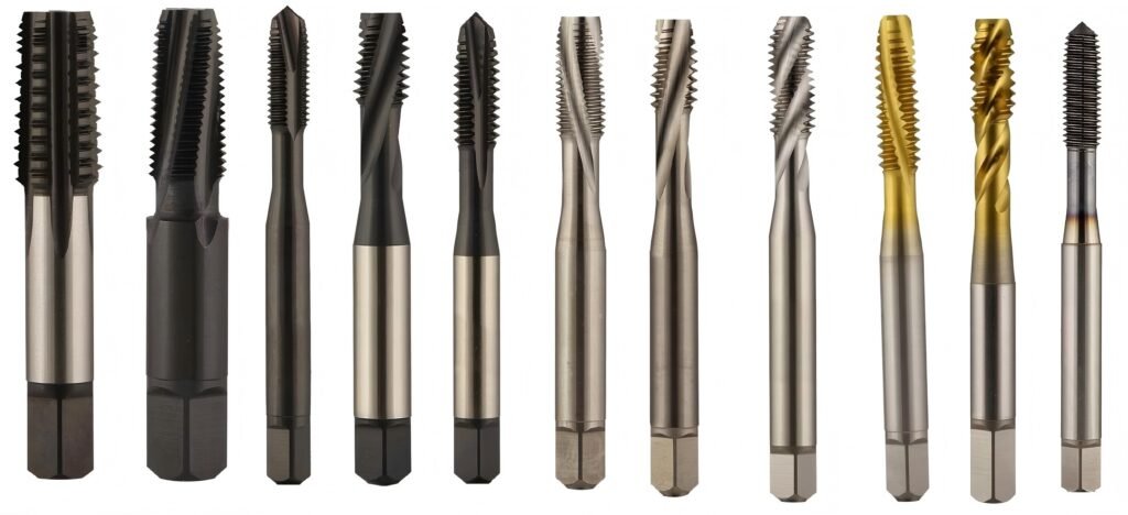
New & Notable: Series at a Glance
If you’re standardizing or refreshing your tap library, start here. These are the most requested Yamawa families for stainless, aluminum, alloy steels, and heat-resistant alloys. (Full catalog available in the downloads.)
Series Overview (News Block)
Series | Hole Type (Blind/Through) | Chip Evacuation (Straight/Spiral/Form) | Material Focus (SS/Al/HRSA) | Coating | Speed Guidance* |
YSP-SUS | Blind / Through | Spiral 40–45° | Stainless steels (austenitic, martensitic) | TiCN | 8–15 m/min (SS) |
YEX-AL | Blind / Through | Spiral 35° / Straight for through | Aluminum & cast Al-Si | DLC | 20–40 m/min (Al) |
YV-PRO | Blind / Through | Spiral 25–35° | Alloy & carbon steels (600–1200 MPa) | TiAlN | 10–25 m/min (steel) |
Y-SHRF | Blind | Spiral 45° ultra-slim core | Thin-wall parts, micro burr control | TiN/TiCN | 6–12 m/min (SS/steel) |
Y-ROLL | Blind / Through | Form (roll) tap | Ductile materials (Al, low-carbon steel) | TiN / DLC | 25–60 m/min (Al/LC steel) |
Y-HRSA | Blind / Through | Spiral 30° reinforced | Ni-based & heat-resistant alloys | TiAlN nano | 4–10 m/min (HRSA) |
*Speed guidance is indicative; always validate with coolant/MQL conditions, rigidity, and machine capability.
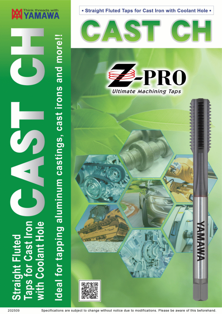
CAST CH Straight Fluted Taps for Cast Iron with Coolant Hole
Material Playbooks
Stainless Steel (Prevent Cold Welding & Chip Wrap)
Austenitic grades (304/316) smear, work-harden, and cold-weld to rake faces. The fix is high lubricity plus a geometry that breaks chips before they braid around the shank.
Recommended: YSP-SUS spiral 40–45° for blind holes; YV-PRO straight or 25–30° spiral for through holes where chip evacuation is easier.
Coatings: TiCN for lubricity and wear; consider DLC on low-Si stainless when galling dominates.
Tactics: Push feed confidently (synchronous tapping preferred), avoid dwell at reversal, use high-performance tapping oil or MQL with EP additives. Keep bottom-hole straightness and finish high—poor holes multiply torque spikes.
Aluminum (Evacuate, Avoid Adhesion)
Al alloys, especially high-Si cast grades, favor a high rake and smooth chip flow. Built-up edge (BUE) is the enemy.
Recommended: YEX-AL with polished flutes (spiral for blind, straight for through); Y-ROLL form taps for ductile wrought alloys where no chips is the best chip.
Coatings: DLC to cut adhesion and keep edge clean; uncoated polished options for gummy grades.
Tactics: Higher cutting speeds, through-spindle coolant or MQL, and generous chamfers. For form taps, increase bottom-hole size vs. cut taps and mind machine torque limits.
Alloy & Carbon Steels (Balance Wear and Toughness)
Medium carbon and quenched/tempered steels respond well to moderate rake, strong land support, and abrasion-resistant coatings.
Recommended: YV-PRO (TiAlN) for through and blind; Y-ROLL on low-carbon ductile steels for maximum tool life and zero chip risk.
Coatings: TiAlN for hot hardness; TiN/TiCN for lower alloy steels when lubricity matters more than heat.
Tactics: Keep speed in the middle of the range, use soluble oils with high EP performance, and ensure rigid, error-free synchronous feed.
Heat-Resistant Alloys (Control Heat, Control Torque)
Ni-base and Co-base alloys push temperature and torque up quickly. The geometry must keep chips short and the coating must survive heat.
Recommended: Y-HRSA reinforced spiral, robust core with controlled rake.
Coatings: TiAlN nano or similar for thermal stability.
Tactics: Lower surface speed, abundant high-pressure coolant, perfectly rigid rigid-tapping cycles (no dwell). Keep stick-out minimal.
Geometry & Coatings: What Changes and Why
Back Taper (Relief): A gentle back taper reduces flank rubbing in the thread, keeping torque stable late in tool life.
Rake & Spiral Angle: Blind holes want a higher spiral (35–45°) to lift chips; through holes tolerate lower spiral or straight for strength.
Point Styles: Semi-bottoming points for blind holes reduce torque at entry; gun points for through holes push chips forward.
Form (Roll) Tap Tooth Form: Displaces material instead of cutting, creating compressive threads with excellent root strength—zero chips, but requires the correct bottom-hole size and a ductile substrate.
Coatings:
TiN: Universal, low friction, easy to spot wear.
TiCN: Higher hardness and lubricity—great in stainless.
TiAlN: Hot hardness and oxidation resistance for steels/HRSA.
DLC: Ultra-low friction to fight adhesion in Al and some SS.
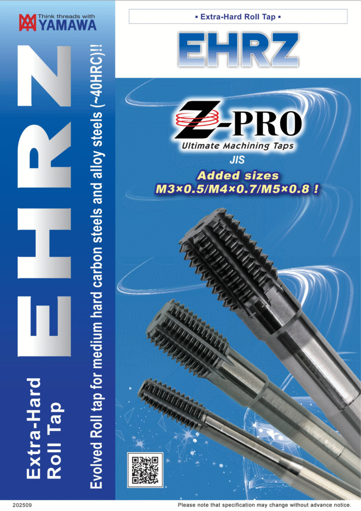
Yamawa Tap Z-pro
Process Strategy
Coolant Strategy:
Dry: Rare; only consider on free-cutting aluminum with DLC and perfect chip evacuation.
MQL: Excellent for Al and low-carbon steels; pair with polished flutes.
Flood/HP Coolant: Preferred for stainless and HRSA; aim streams into flutes on blind holes.
Tapping Method:
Rigid/Synchronous Tapping: Best for consistent pitch and torque; check spindle-Z following error and servo tuning.
Floating/Tension-Compression Holders: Add forgiveness on legacy machines; pick a short, stiff holder to minimize pitch error.
Speed Envelope: Start mid-range per material table, then tune:
Increase speed if torque is flat and chips are short/clean.
Decrease speed if torque spikes at reversal or chips smear.
Depth & Chamfer:
Use a proper chamfer length (2–3P for through, 2P for blind).
Maintain generous countersinks to prevent first-thread burrs.
Respect max depth for spiral geometry—over-deep blind holes trap chips and spike torque.
Performance: What to Expect (Success Rate, Torque, Life)
Tapping Success Rate: With correct bottom-hole, rigid feed, and the right series, expect >98% first-pass success on production runs.
Torque Curves: Stainless and HRSA show a rising torque profile toward reversal; controlling chip length and lubrication flattens this rise. Watch peak torque—keep it within machine and holder limits.
Tool Life (Holes):
Y-ROLL (Al/LC steel): thousands of holes per tap in production due to no chip load on the edge.
YSP-SUS (SS): hundreds to low thousands depending on grade, lubrication, and depth.
Y-HRSA (Ni-base): tens to a few hundred; stability and cooling dominate outcomes.
Standards & Specifications
Thread Standards: JIS, ISO, DIN, UNC/UNF, G (BSPP), Rp (ISO 7/1), NPT/NPTF (availability by series).
Accuracy Grades: Classifications per standard; select tighter classes for gauge-critical work.
Shank/Drive: Per DIN/ISO with square drive compatibility for rigid or floating holders; verify overall length for blind holes with fixtures.
Marking: Series, size, coating, and lot for traceability.
Bottom-Hole Diameters (Cut vs. Form Taps)
Correct bottom-hole size is the fastest way to reduce torque and prevent broken taps. Form taps require larger holes than cut taps.
Bottom-Hole Recommendations
Thread | Pitch (mm) | Cut Tap Drill Ø (typ.) | Form Tap Drill Ø (Al/LC Steel) | Notes |
M3 × 0.5 | 0.50 | 2.5 mm | 2.7–2.8 mm | Go larger in soft Al to lower torque |
M4 × 0.7 | 0.70 | 3.3 mm | 3.5–3.6 mm | Check % of thread; 65–70% is fine for form |
M5 × 0.8 | 0.80 | 4.2 mm | 4.5–4.6 mm | Rigid tapping strongly recommended |
M6 × 1.0 | 1.00 | 5.0 mm | 5.4–5.5 mm | Watch torque on deep blind holes |
M8 × 1.25 | 1.25 | 6.8 mm | 7.3–7.4 mm | Increase MQL flow for form tapping |
Values are typical starting points—verify with your gauge class, alloy, and thread engagement target.
Troubleshooting: Fast Causes & Fixes
Faults & Countermeasures
Symptom | Likely Causes | Countermeasures |
Chipping / Broken Tap | Undersized bottom-hole; poor lubrication; pitch mismatch; excessive stick-out | Enlarge drill for form taps; improve coolant/MQL; verify rigid tapping and compensation; shorten holder |
Seizing / Cold Welding (SS/Al) | Wrong coating; low lubricity; chip packing | Switch to TiCN (SS) or DLC (Al); increase flow/EP; raise spiral angle for blind holes |
Cannot Enter / High Entry Torque | No chamfer/countersink; entry burrs; misalignment | Add 90° countersink; deburr; verify spindle-Z alignment; use gun point for through holes |
Incomplete Thread Form | Bottom-hole too large (cut) or too small (form); wear | Correct drill Ø; replace worn tap; check gauge class |
Rough Finish / Burrs at Exit | Chips carried into thread; reversal dwell; low speed in soft alloys | Increase speed in Al; continuous feed, no dwell; improve evacuation (spiral or through holes forward chip) |
Pitch Error / Tight Go Gauge | Non-synchronous feed; floating holder too soft; thermal growth | Use rigid tapping; stiffer holder; warm up spindle; verify pitch compensation |

FAQs
Q1: Spiral or straight flutes for stainless blind holes?
Spiral at 35–45°. It lifts chips out of the hole before reversal, reducing torque spikes and cold welding. Pair with TiCN for lubricity.
Q2: When should I switch to a form (roll) tap?
When the material is ductile (Al, low-carbon steels) and you want zero chips, stronger thread roots, and long tool life. Ensure the larger bottom-hole Ø and adequate machine torque.
Q3: Why does my torque spike at reversal?
Chips are packing or rubbing at the crest. Increase spiral angle for blind holes, improve lubrication, and avoid dwell. If possible, raise speed slightly to shorten chips.
Q4: Do I need DLC in aluminum every time?
No—but DLC greatly reduces BUE in gummy grades and cast Al-Si. In very free-cutting wrought alloys, polished uncoated can work well too.
Q5: How do I choose speed for HRSA?
Start low (4–10 m/min), prioritize coolant pressure and stability, and monitor torque. In HRSA, heat control and rigidity beat speed every time.
Q6: My go gauge passes but finish looks torn—why?
Likely chip re-cutting or adhesion. Increase lubrication, consider DLC (Al) or TiCN (SS), and verify bottom-hole finish and straightness.