Table of Contents
Core Pain Points
Built-Up Edge (BUE) & smeared burrs on stainless
Austenitic grades (304/316) love to work-harden, shed long stringers, and weld to edges. BUE snowballs into unstable chip formation, rising thrust, and rough hole walls.
Blackened/heat-tinted hole walls
Stainless retains heat; if chips stay in the cut or coolant can’t reach the shear zone, you’ll see oxide tinting, washboarding, and taper.
Tool-life scatter during frequent changeovers
High-mix/low-volume lines switch diameters and materials often. If drills aren’t matched to the heat, coolant, and clamping reality of each job, life varies wildly—driving up cost and downtime.
Cost of changeovers and tool inventory
Solid drills lock cost into every diameter/L/D. Frequent swaps multiply setup minutes and WIP risk.
What’s New: Why KCMS40 + KSEM PLUS Works
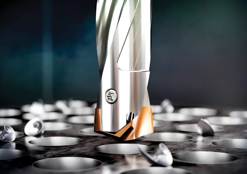
Coating & Substrate: Balanced anti-adhesion, wear, and toughness
- Anti-adhesion top layerresists nickel-rich stainless “welding.” The smoother, hard, low-affinity surface disrupts BUE nucleation so chips separate cleanly.
- High-hot-hardness multilayer stackkeeps edge integrity under intermittent load and marginal coolant.
- Tough, fine-grain carbide substrateunderneath absorbs micro-chipping from hard inclusions in alloy steels and from interrupted entries/exits (cross holes, keyways).
- Thermal management: reduced friction + internal coolant means lower heat at the margin, less oxide tint, and better roundness.
Tip/M.D. Geometry: Load sharing & low thrust
- Split-point / self-centering chisel reduces walking and thrust—especially on thin or “springy” setups.
- Progressive rake + honed cutting edges balance sharpness (for stainless) with edge strength (for quenched steels).
- Refined margin lands & micro-clearance stabilize the hole with minimal rub, which fights heat-tinting.
- Optimized flute polish (on the head) promotes evacuation of ductile stainless chips at lower pressure.
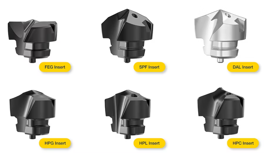
Modular Architecture: Reuse the body, swap only the head
- Quick head changes slash changeover minutes versus pulling a complete solid drill.
- Body reuse amortizes the expensive carbide body across many heads/diameters; one shank, multiple heads.
- Tighter inventory: keep a compact library of heads (diameter steps, edge preps, materials) that mate to the same body.
- Consistent gage length: repeatable Z after head change reduces re-touch time.
Selection & Application Window
Diameter / L/D / Coolant Mode
- Diameters:Common range from small (≤8 mm) to medium/large (e.g., 25 mm+), with matching KSEM PLUS heads for each body.
- Depth-to-Diameter (L/D):
Up to 3×D: forgiving; flood or MQL viable on free-cutting steels; internal coolant recommended on stainless.
5×D: internal coolant strongly recommended; chip evacuation becomes the constraint.
>5×D: confirm pilot/guide strategy, higher pressure, and chip control before release.
Coolant options:
Internal through-coolant (preferred): stable control of temperature + chip packing.
MQL: workable in short-chipping alloys; validate burrs and dimensional drift.
Flood/Emulsion: fine for short-holes or free-cutting alloys; avoid in deep blind holes without evacuation.
Work Materials: What “good” looks like
SUS304/316 (Austenitic): Expect lower cutting speeds and a strong focus on chip control; the KCMS40 head’s anti-adhesion layer is the star here.
Alloy steel (e.g., 4140/42CrMo, normalized): Speeds can rise; watch for garnet-like inclusions.
Quenched & tempered steels (e.g., 42CrMo Q&T): Control heat at margin; keep edges honed; ensure coolant reaches the point.
Quick Application Window (reference)
Range | 304/316 Stainless | Alloy Steel (e.g., 4140) | Q&T Steel (e.g., 42CrMo) |
L/D ≤ 3×D | Excellent with through-coolant; good with rich emulsion | Excellent (all coolant modes) | Good–Excellent with through-coolant |
3–5×D | Recommended: through-coolant; pilot if needed | Very good; through-coolant preferred | Good; through-coolant + stable clamping |
>5×D | Case-by-case; verify pressure & chip plan | Possible with high-pressure IC | Possible but validate carefully |
Conservative Start Parameters (Use These to Launch Safely)
Start mid-range for your setup rigidity and coolant capability. After achieving stable chips and <Ra target>, increment Vc by ~5–10% or f by one step, not both at once.
Startup Parameters (placeholders/ranges; refine by actual head diameter & setup)
Material | Vc (m/min) | f (mm/rev) | Coolant | Notes |
SUS304 | 30–55 | 0.08–0.20 | Through-coolant / rich emulsion | Start on the lower Vc if coolant is marginal; watch BUE. |
SUS316 | 25–50 | 0.08–0.18 | Through-coolant mandatory >3×D | Stainless-first geometry helps; target short, tight chips. |
42CrMo (normalized) | 55–90 | 0.12–0.24 | Emulsion or through-coolant | Increase Vc if chips are tight & walls are bright. |
42CrMo (Q&T) | 45–80 | 0.10–0.22 | Through-coolant | Keep margins cool; look for micro-chipping early. |
Tip: For small diameters (<6 mm), bias toward the lower end of f to avoid wandering; for large diameters (>20 mm), prefer stable f to maintain chip thickness and avoid rubbing
The Math: Modular vs Solid—Cost & Uptime
When you change diameters and materials often, time and amortization dominate. Here’s a simplified model to sanity-check your choice.
Assumptions (example—adjust to your shop)
Solid carbide drill price is higher per tool; regrinds add cost + variability in length.
Modular body is reusable; you swap lower-cost heads.
Changeover time (pulling the whole tool) is longer than head-only change.
Downtime value includes operator + machine rate.
Cost per Hole Snapshot (illustrative placeholders)
Metric | Solid Carbide Drill | KSEM PLUS Modular (KCMS40 head) |
Tool/Body cost | High (per diameter) | Body cost amortized; head cost moderate |
Regrind cycles | 2–4 (adds length variability) | Swap head; body stays constant |
Typical changeover | 6–12 min (full tool swap) | 2–5 min (head swap) |
Life (holes/head)* | N holes | N to N+X (stable in stainless) |
Cost per hole (tooling only) | Higher if many diameters | Lower when body reused |
Cost per hole (with downtime) | Sensitive to changeover | Reduced via quick swaps |
*Life varies with diameter, L/D, coolant pressure, and setup rigidity. What matters in stainless is stability—modular heads let you maintain edge tech while keeping gage length consistent.
Takeaway: If you run high-mix SKUs or shift between 304/316 ↔ 42CrMo frequently, modular typically wins on total cost per hole and OEE, not just on tool price.
Risks & Boundaries (What Can Bite You)
Thin-wall parts & low-rigidity workholding: Even with low-thrust geometry, thin shells spring. Pilot/backup, reduce f slightly, and favor sharp edges; verify exit burrs.
Low coolant pressure in deep holes: Long stainless chips will pack. Use pecking strategies sparingly (can re-work-harden the bore). Prioritize through-coolant and proper filtration.
Runout/holder choice: Excess runout heats one margin, leading to black walls and tapered holes. Use precision hydraulic or shrink-fit holders; minimize gage overhang.
MQL in austenitic stainless: Viable at shallow L/D; validate burr and tolerance drift before committing.
Troubleshooting & Controls
Quick Fix Matrix
Symptom | Likely Cause | Do This First |
Hole wall black/tinted | Heat from rubbing; chip packing | Check runout (<0.01–0.02 mm), increase coolant flow/pressure, reduce Vc 10%, hold f. |
Large entry/exit burrs | Edge dulling; low feed | Replace head; step f up slightly; add small chamfer or backup plate. |
Oversize/ovality | Runout; deflection at L/D | Improve holder, shorten overhang, reduce f 10%, confirm pilot. |
BUE & squeal in 304/316 | Adhesion; low chip thickness | Raise f one step; lower Vc 10%; ensure rich emulsion or IC; polish chip evacuation. |
Chatter marks | Stackup rigidity | Reduce gage length; clamp closer; try lower f then recover. |
FAQ
Q: How do I correct oversize holes and burrs?
A: For oversize, first check runout and overhang, then trim f by ~10% while holding Vc; if chatter subsides, ramp f back cautiously. For burrs, a fresh head plus a slight increase in f (to maintain chip thickness) helps. On exits, add a backup or program a light chamfering pass if the print allows.
Q: What’s a practical wear criterion and head-swap interval?
A: In stainless, watch for:
Land wear reaching ~0.15–0.20 mm (macro) or onset of BUE re-appearance.
Rising spindle load and hotter/tinted margins.
Set a conservative holes-per-head counter from your first stable run. Swap before the scatter zone to keep Cp/Cpk healthy. Keep a retired-head gage log to learn your site-specific trigger.
Q: Can this run Inconel or other Ni-base superalloys?
A: The geometry and anti-adhesion layer help, but superalloys push heat and notch wear much harder than 316. If you must, treat it as a separate process window: very modest Vc, disciplined f, high-pressure IC, impeccable runout, and a strict wear counter. Validate in a controlled trial before release.
Practical Setup Tips (Don’t Skip These)
Measure runout at the head, not just the holder. You’re chasing margin heat—every micron matters.
Coolant discipline: For stainless, prioritize through-coolant with clean filters; if emulsion, run rich and verify pressure at the spindle.
Program ramps sensibly: Avoid pecking unless chip evacuation truly demands it; pecks can re-work-harden stainless.
Edge prep choice: For gummy stainless, a light hone + anti-adhesion top layer is your friend; for Q&T steels, ensure enough hone to resist micro-chipping.
Document the stable window: Once chips are short/silver and hole Ra meets spec, freeze Vc/f as a “green sticker” recipe by diameter and L/D.

Procurement & Alternatives
If you’re deploying this across a high-mix line, keep spare KSEM PLUS™ heads in the most common diameters and L/D ratios, plus at least one extra body per spindle size so you can stage offline setups.
HNCarbide (stock / lead time / after-sales)
- Available equivalents/alternatives:HNCarbide supplies compatible modular drill solutionsfor stainless and alloy steels, with anti-adhesion coatings and through-coolant bodies.
- Lead times:Standard diameters typically ex-stock or short lead.
- Support:Application review, startup parameter tuning, and failure analysis photos welcome—get a stable window, then standardize.
Recommended holders & coolant hardware
- Holders:Precision hydraulic or shrink-fit for low runout, especially >3×D
- Coolant fittings:Confirm O-ring condition, pressure capability, and that your machine’s tool change does not nick the coolant face. Leaks = heat.